Custom thermoformed packaging
Custom trays, inserts and lids.
Develop thermoformed packaging around your product. See how the lid, insert and base work together in the structure example below.
Lid, insert and base
Lid above, eight-position insert in the middle, base below.
Scroll sideways to explore the images. Select an image to enlarge it.
Packaging examples
Open a photo to inspect its compartments, rim and closure.
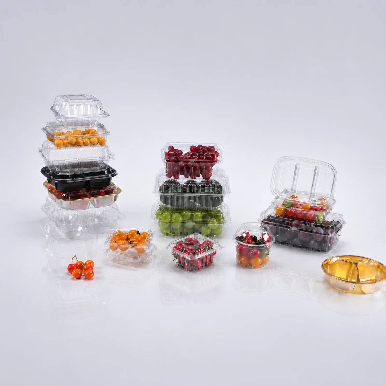
Which lid shape leaves room for your fruit?Share fruit size and fill weight, then check the closed pack with the actual contents.
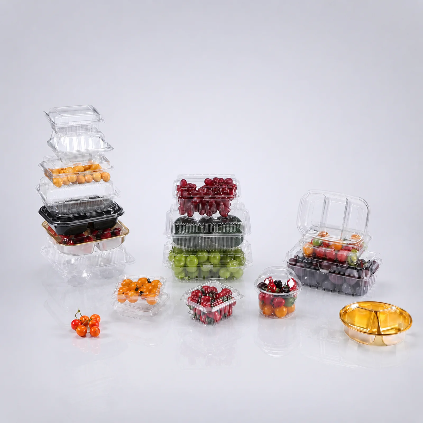
How much height does the filled pack need?Compare shallow and tall formats against your product and outer carton dimensions.
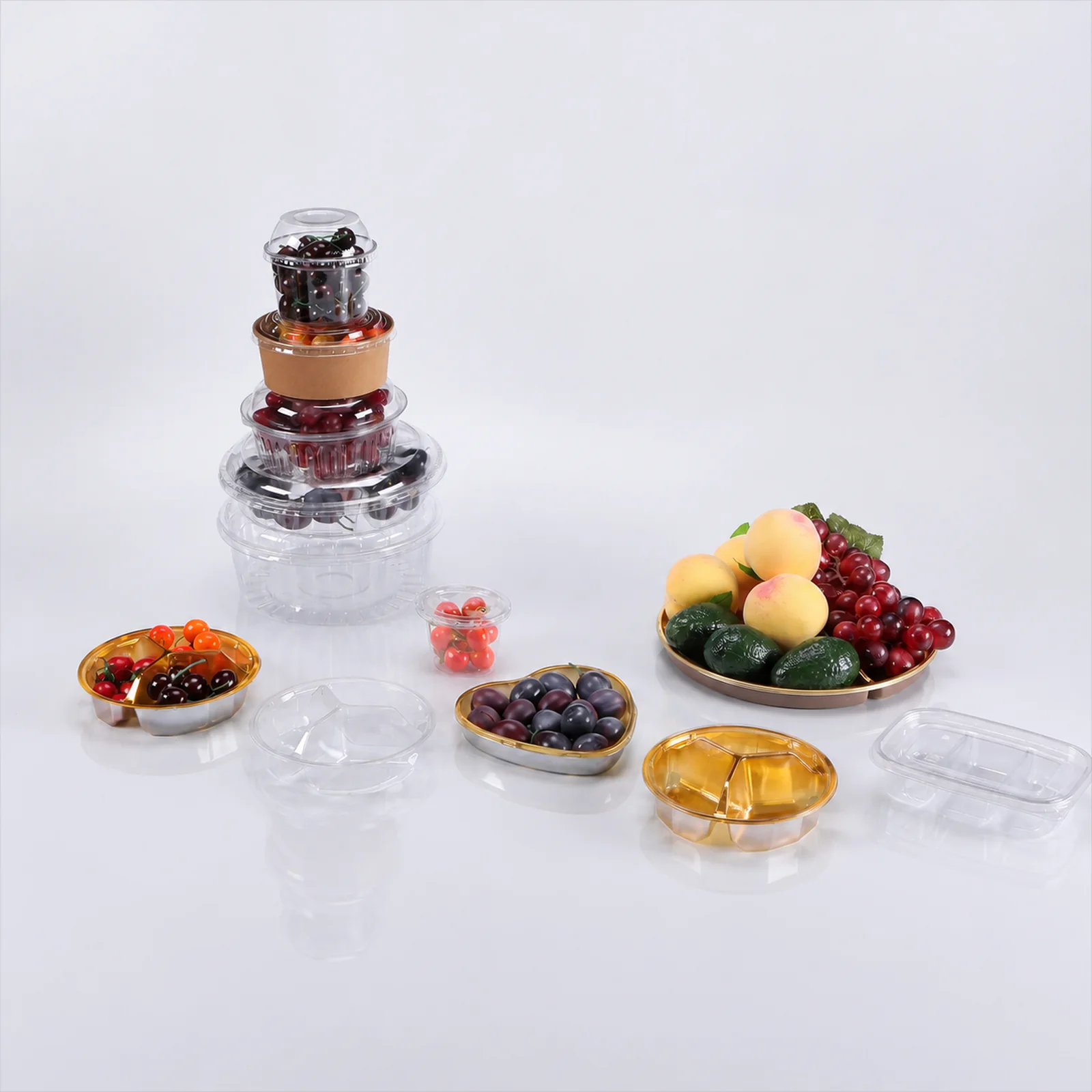
Should the contents stay together or in separate sections?Describe the mix and portion size to discuss an open or divided tray.
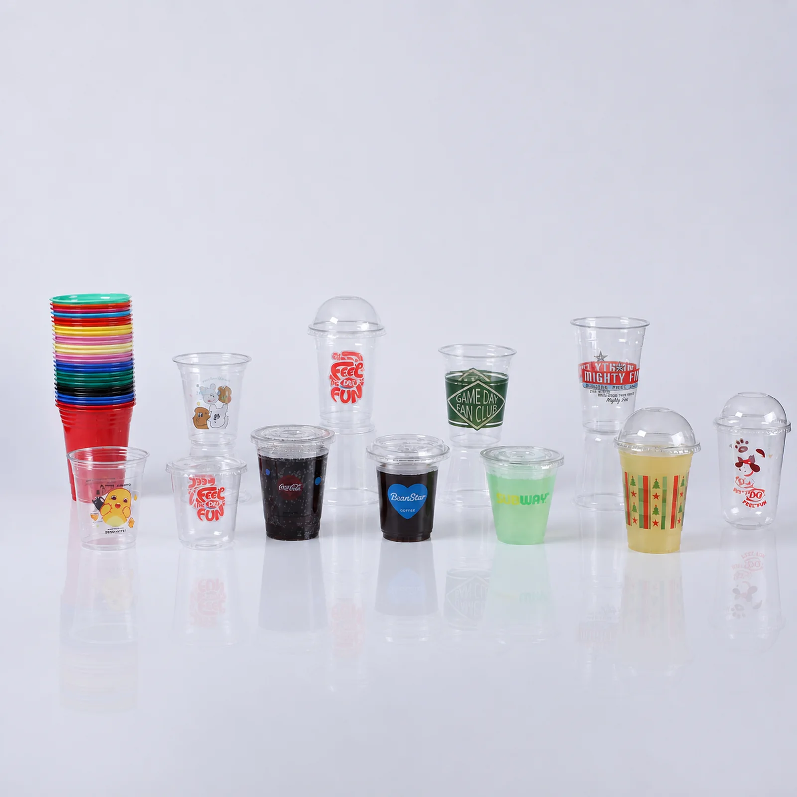
Does the cup need a flat lid or space under a dome?Describe the contents and opening needed; check the chosen lid on the cup sample.
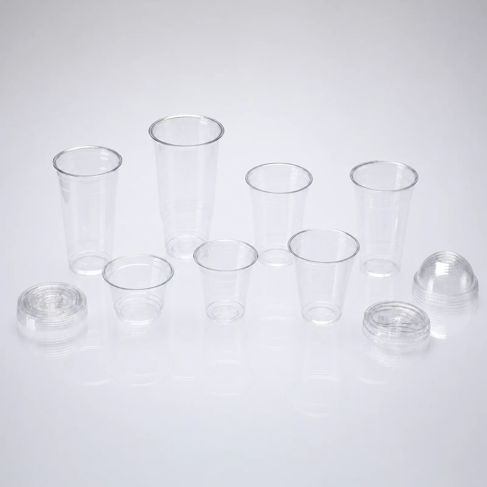
Which cup rim and lid need to fit together?Provide both references or samples so the pairing can be checked.
Overview
Define the product and packing method.
Add the count or measurements if you know them.
Project view
Review the shape where it matters.
In the mold photos below, open “Rounded cavities and separators”. Select the two numbered points to review a cavity wall and the outer edge. The other views show separate layouts, machining and polishing.
Scroll sideways to explore the images. Select an image to enlarge it.
Mold shapes and surface work
Look at cavity layouts, edges, machining and polishing. Dimensions and fit are checked against the drawing and sample for your project.
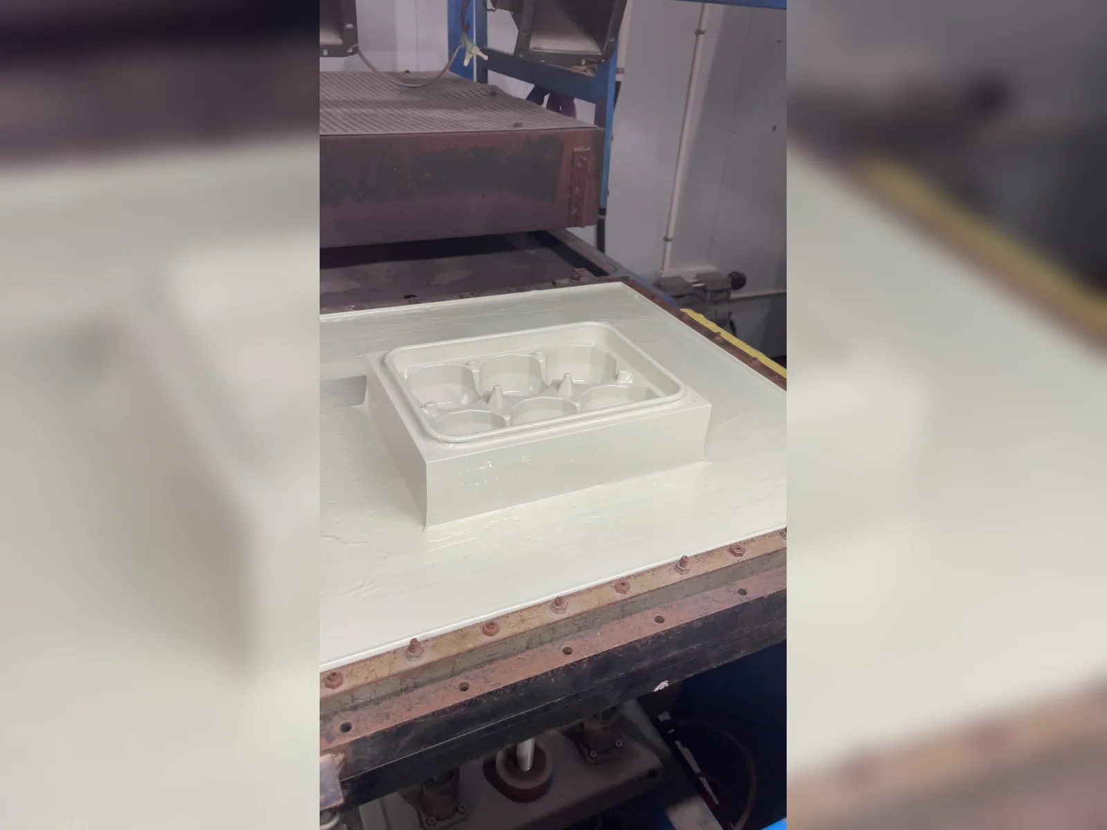
Where should each item sit inside the tray?Describe the product size and count to review the recesses and raised separators.
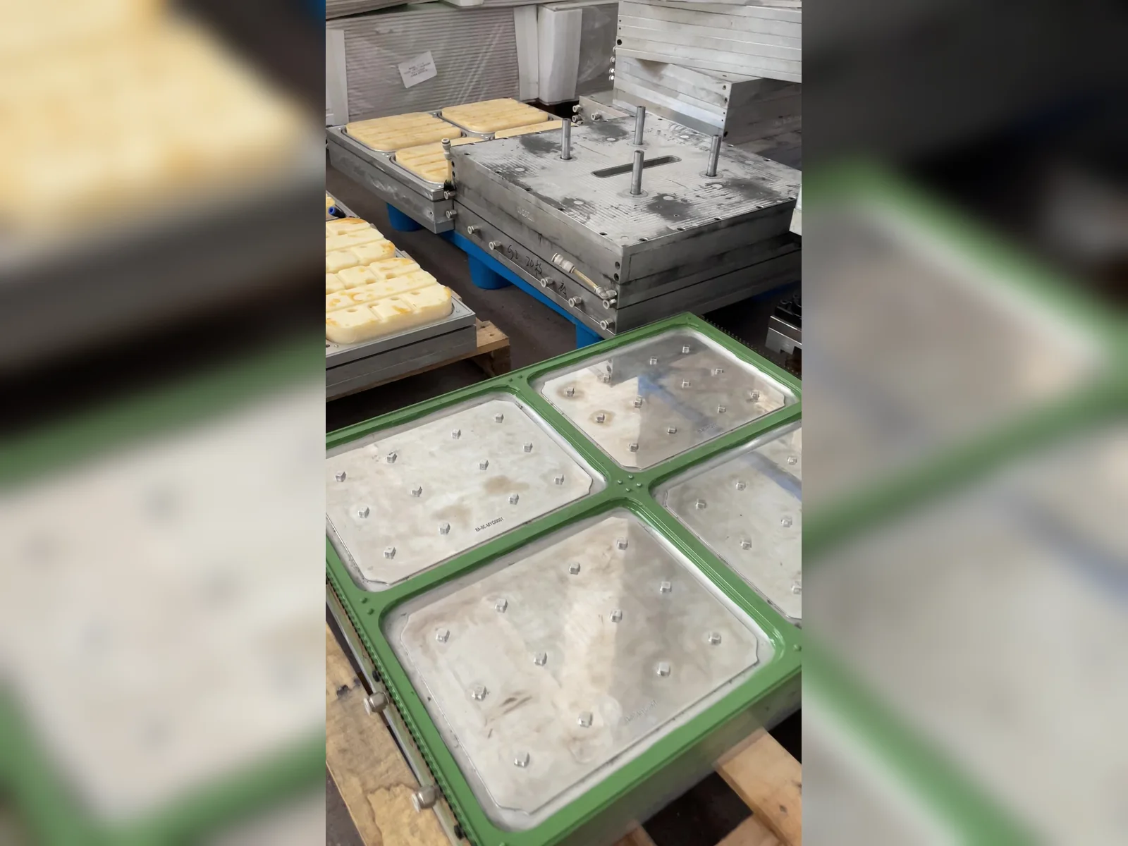
Which outline and repeated details does your pack need?Mark the shape to discuss on your reference photo or drawing.
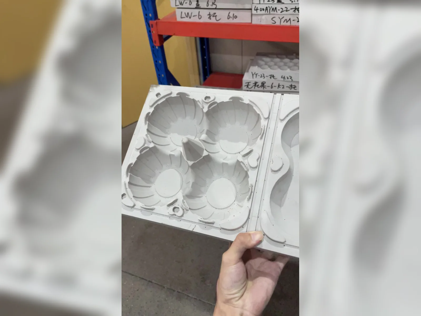
How should the cavities and central divider fit your product?Bring the product dimensions; review contact and clearance with a packed sample.
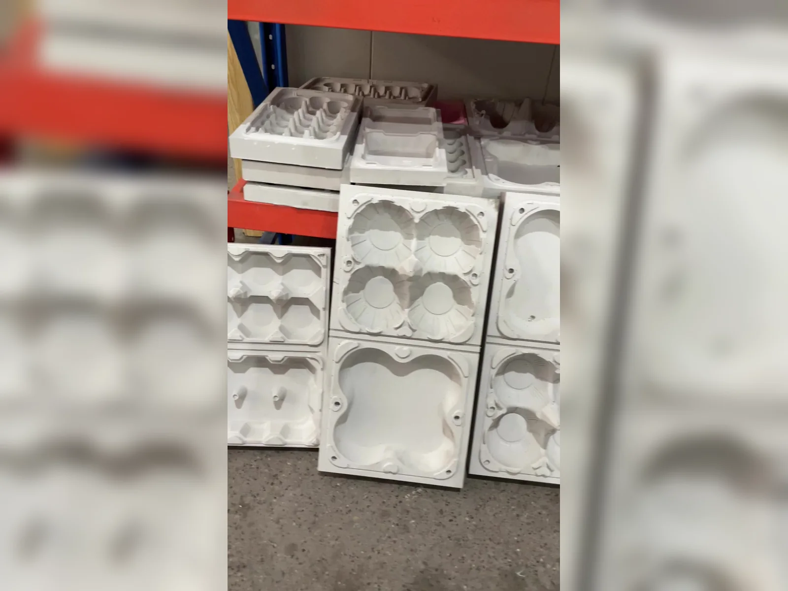
Does your product need individual pockets or an open tray?Compare the visible layouts, then describe how you will arrange the contents.
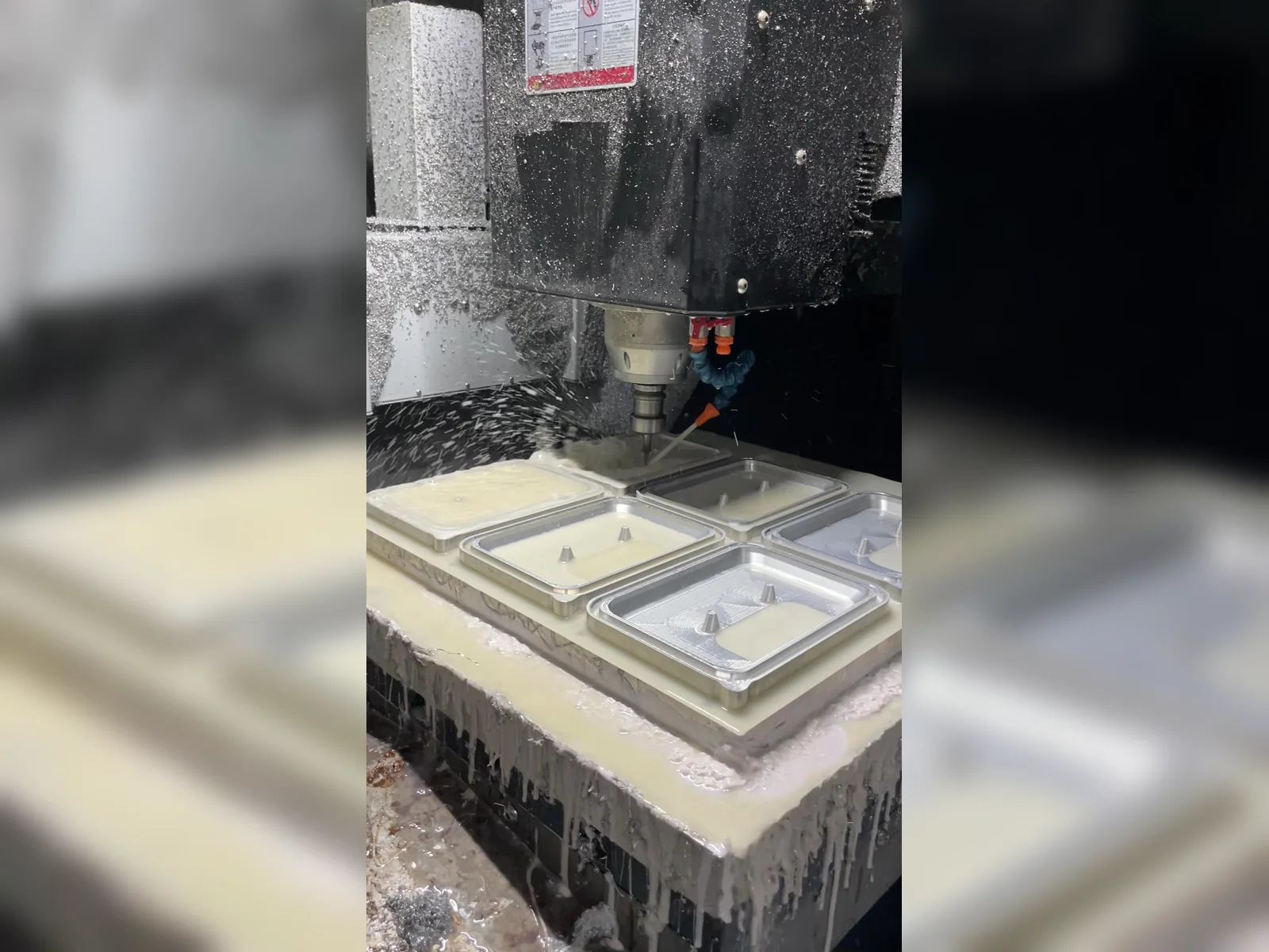
Which cavity edges and raised details need to change?Mark those areas on a drawing before discussing changes to the tool.
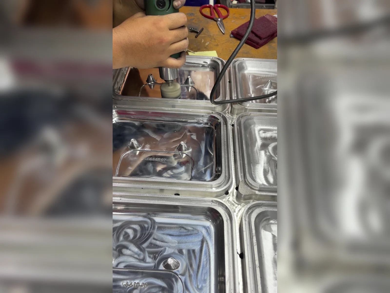
Which surfaces will touch or display your product?Identify those areas; agree the finish using a physical sample.
Scroll to see all 6 views →
Overview
Check function as well as shape.
Overview
Discuss materials and production requirements.
This summary follows your answers. You can edit it in the enquiry form.
Materials, dimensions and fit are reviewed with your product and use conditions.
Overview
Choose a practical starting point.
Check a reference structure
You have a pack or drawing that could fit your product.
- What to bring
- The exact reference, its dimensions and material, plus your product measurements.
- What to review
- Compare product fit, closure, stacking and the outer carton.
- Review output to agree
- A fit checklist showing what matches, what differs and what needs a sample check.
Discuss a specific modification
You have a starting structure and can identify what needs to change.
- What to bring
- The starting reference, the requested changes and the features that must stay fixed.
- What to review
- Check how each change affects the structure, tooling and packing process.
- Review output to agree
- A change list, tooling questions and checks for the revised sample.
Assess a new mold
Your requirements need a new structure, or there is no suitable reference to compare.
- What to bring
- Product measurements or a drawing, packing requirements and the functions to test.
- What to review
- Discuss the proposed structure, tooling scope, ownership and sample revisions.
- Review output to agree
- A proposed tooling scope and sample plan, with cost and timing still to agree.
Unsure where to start? Prepare your product details and describe what you need to resolve.
Process
Read the structure before checking the sample.
Top view: positions and footprint
Eight fruit positions follow a 3–2–3 arrangement. The lid, insert and base have separate outlines; the dimension lines show which footprint belongs to each part.
Side view: support and height
The side views show the shallow lid, the shaped insert and the deeper base. They make the vertical relationship visible before fruit clearance and closure are checked with a filled sample.
These drawings show a structure example. For your product, use the sample to confirm fruit contact, closure fit and the complete pack.
Overview
See the tooling and manufacturing context.
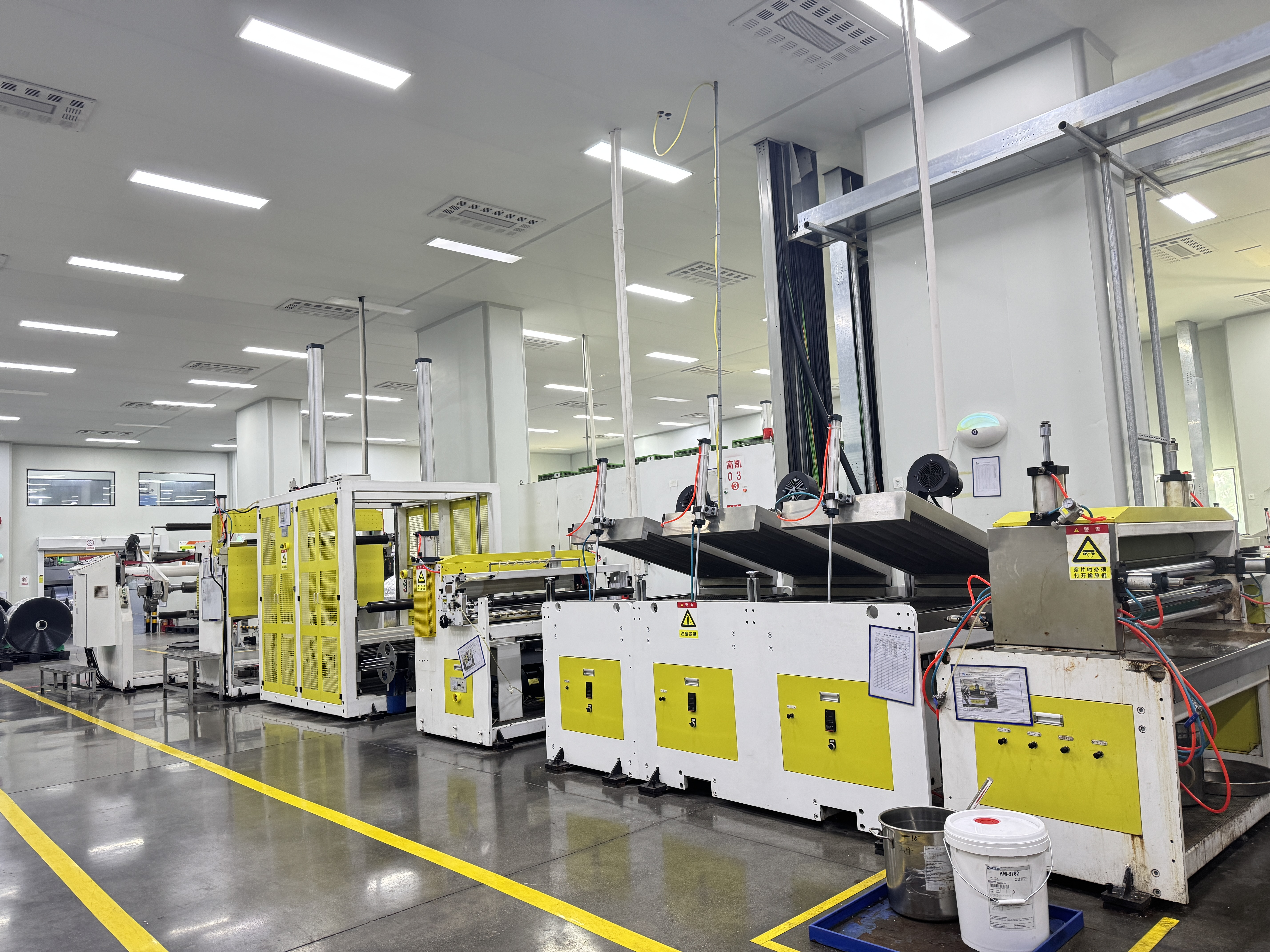
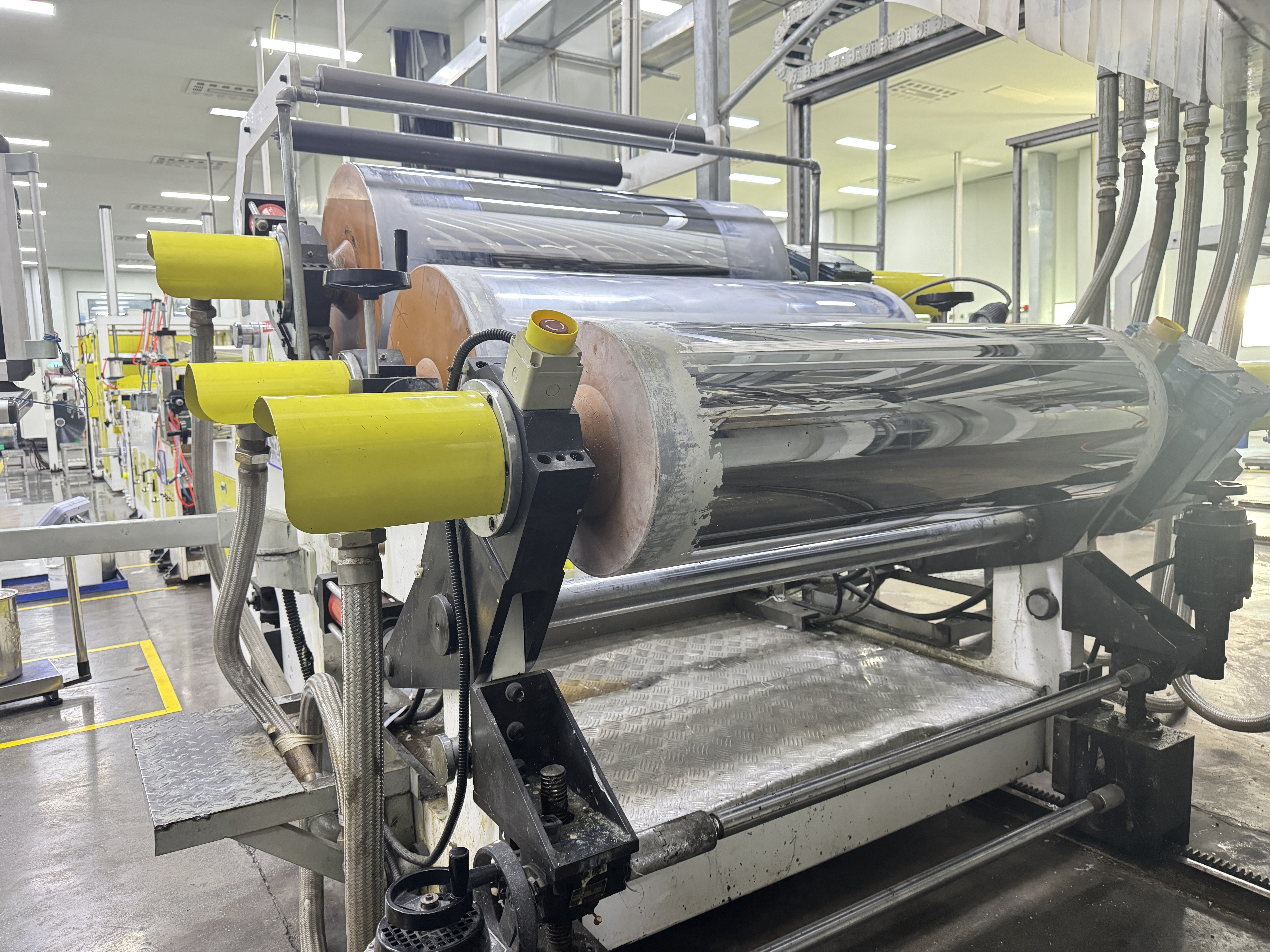
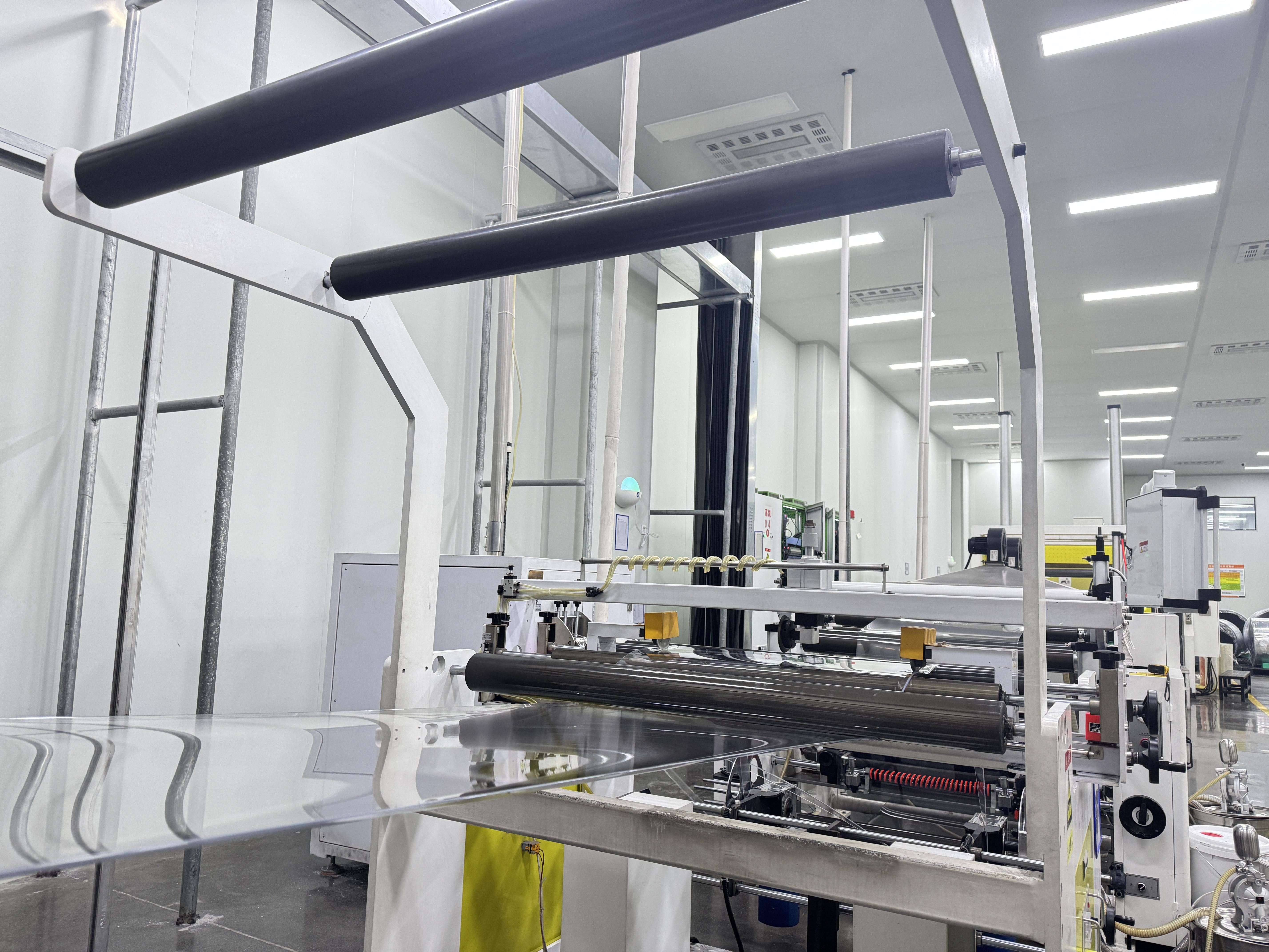
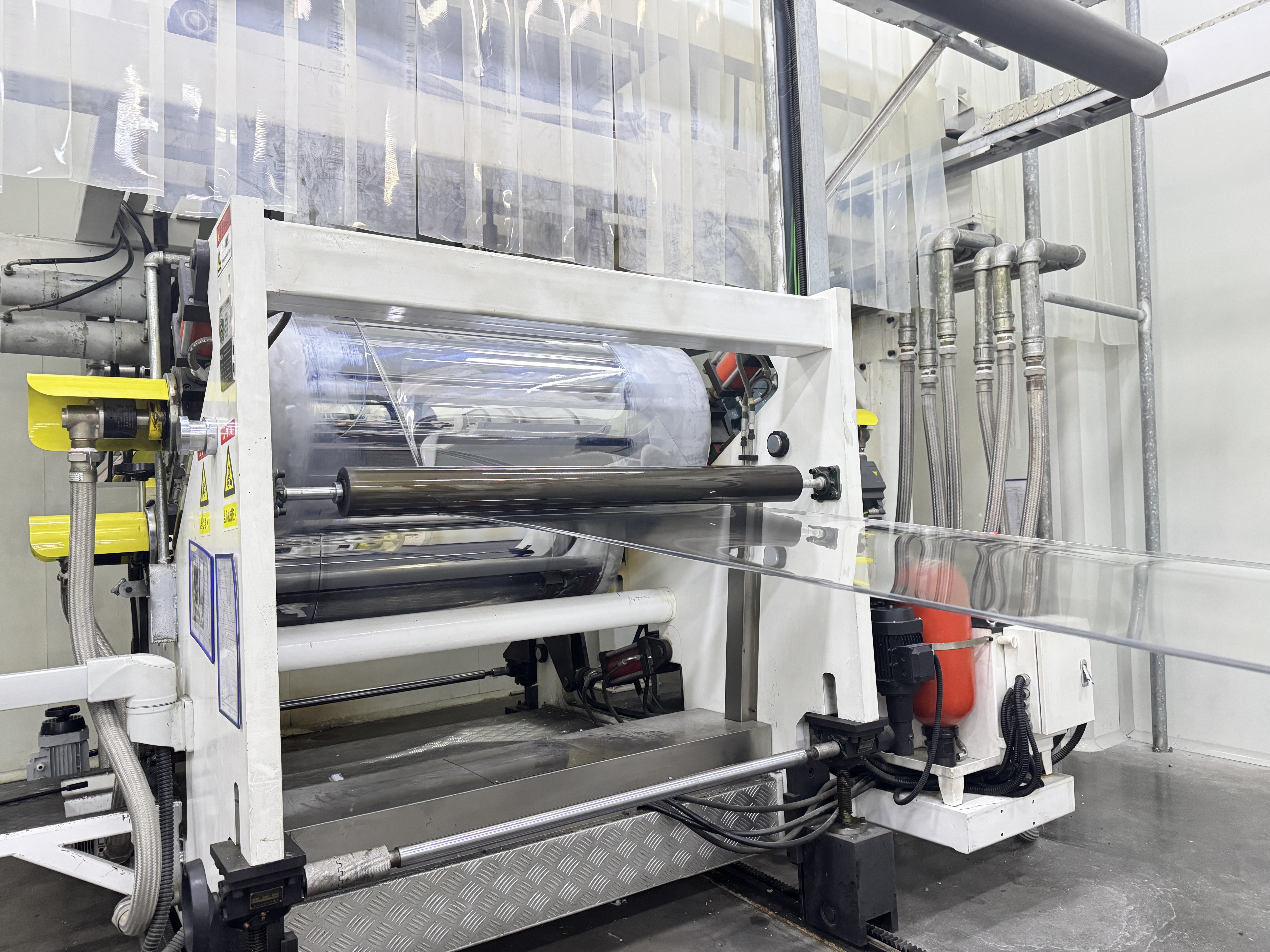
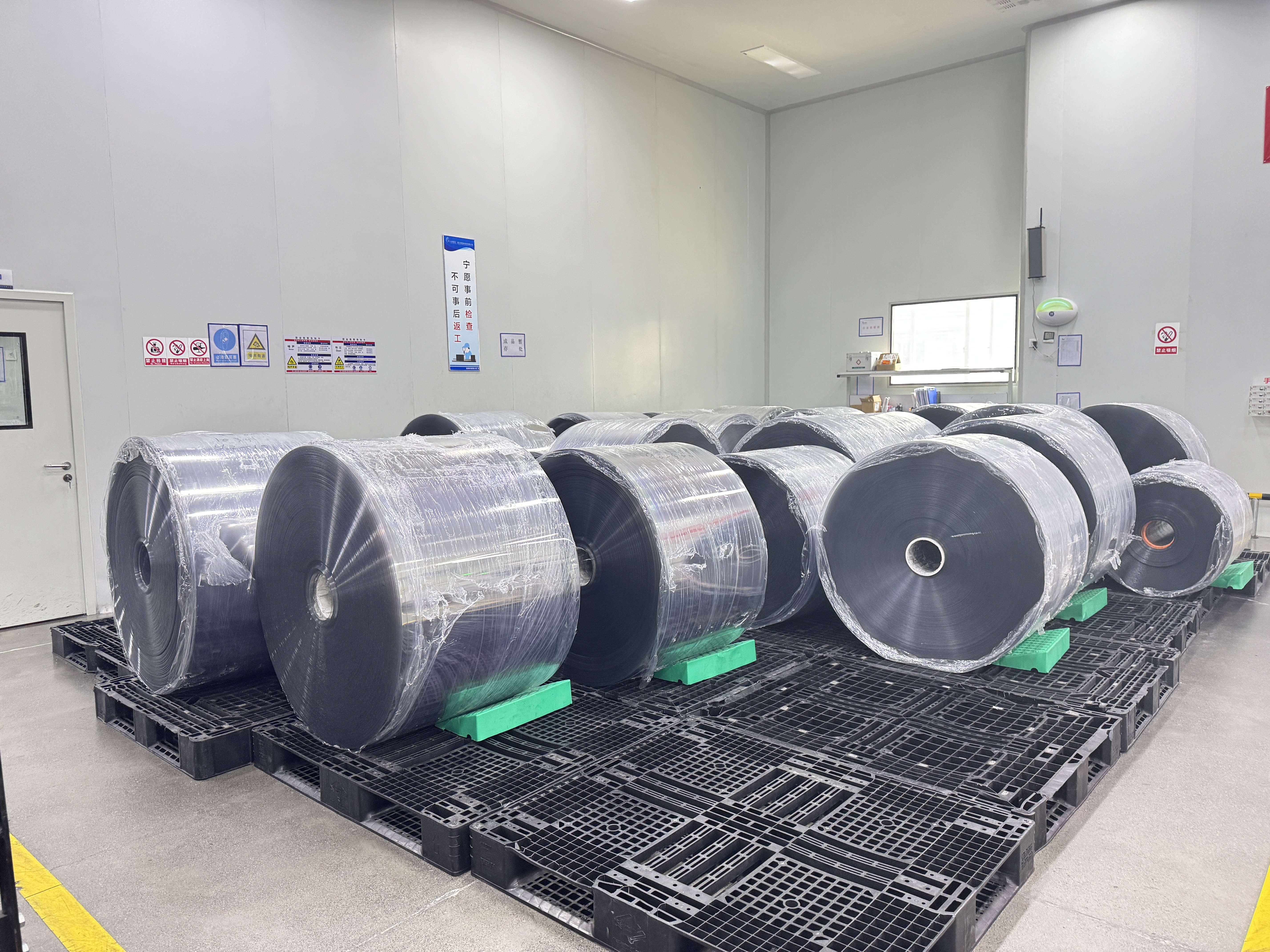
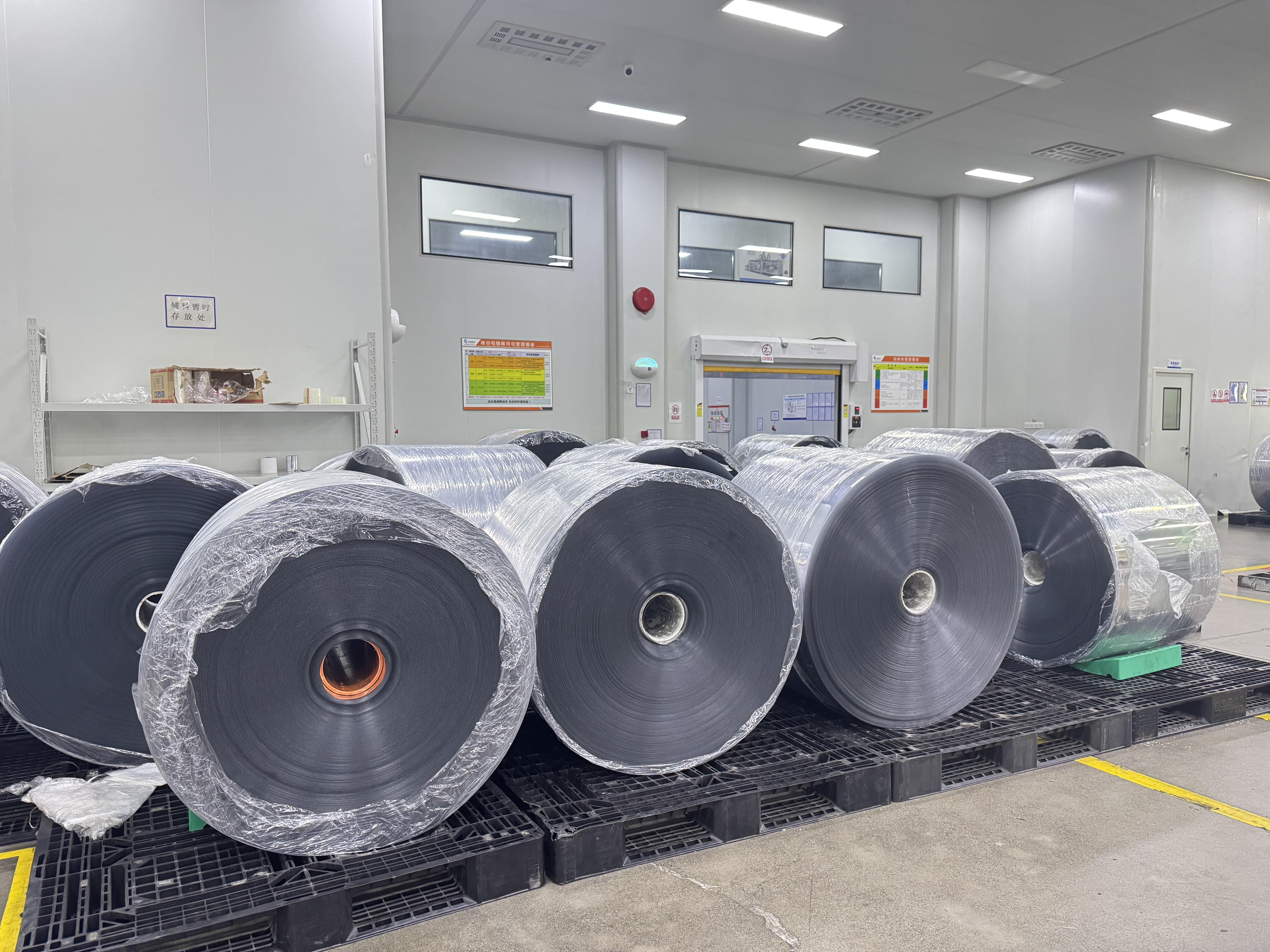
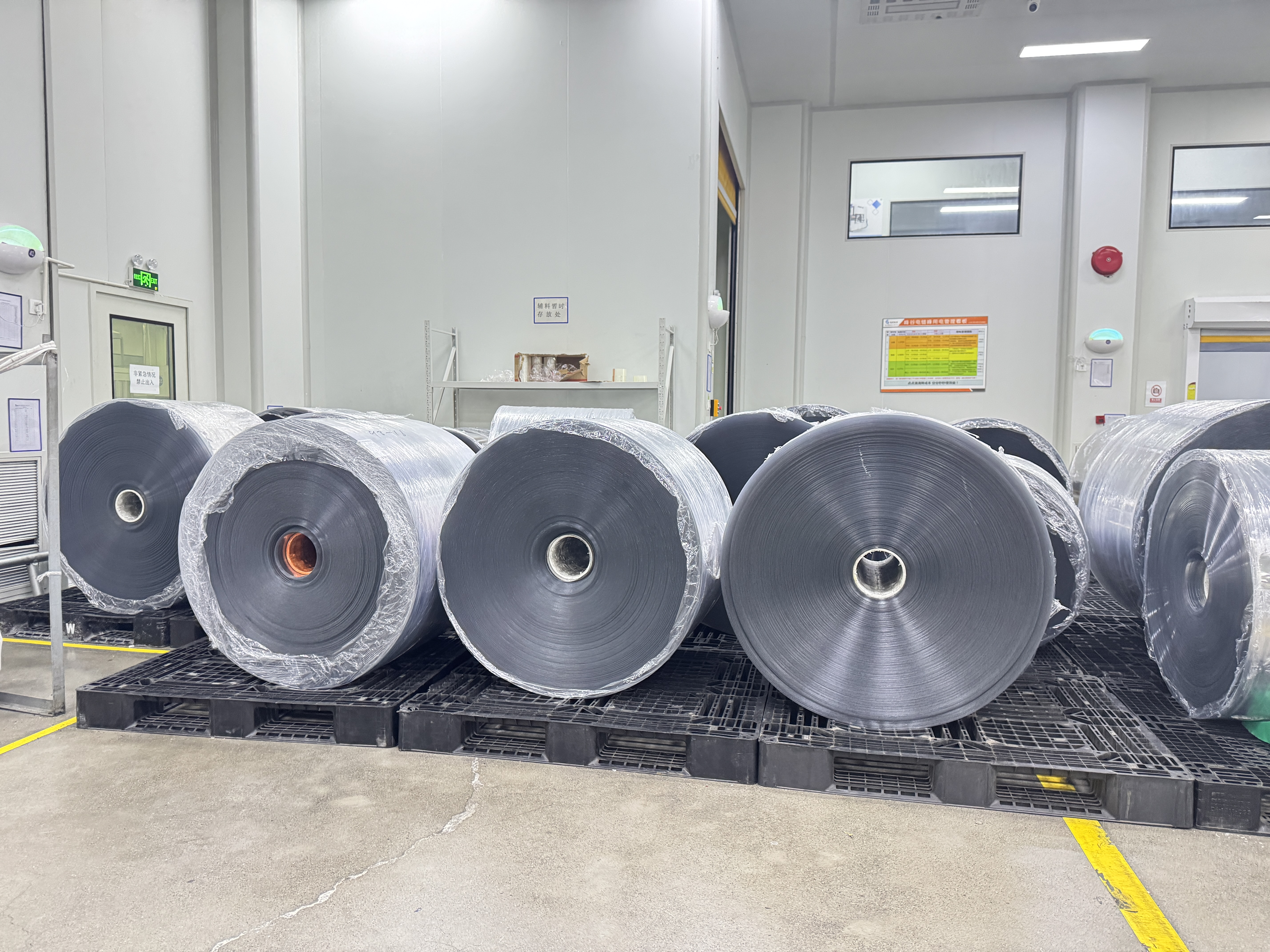
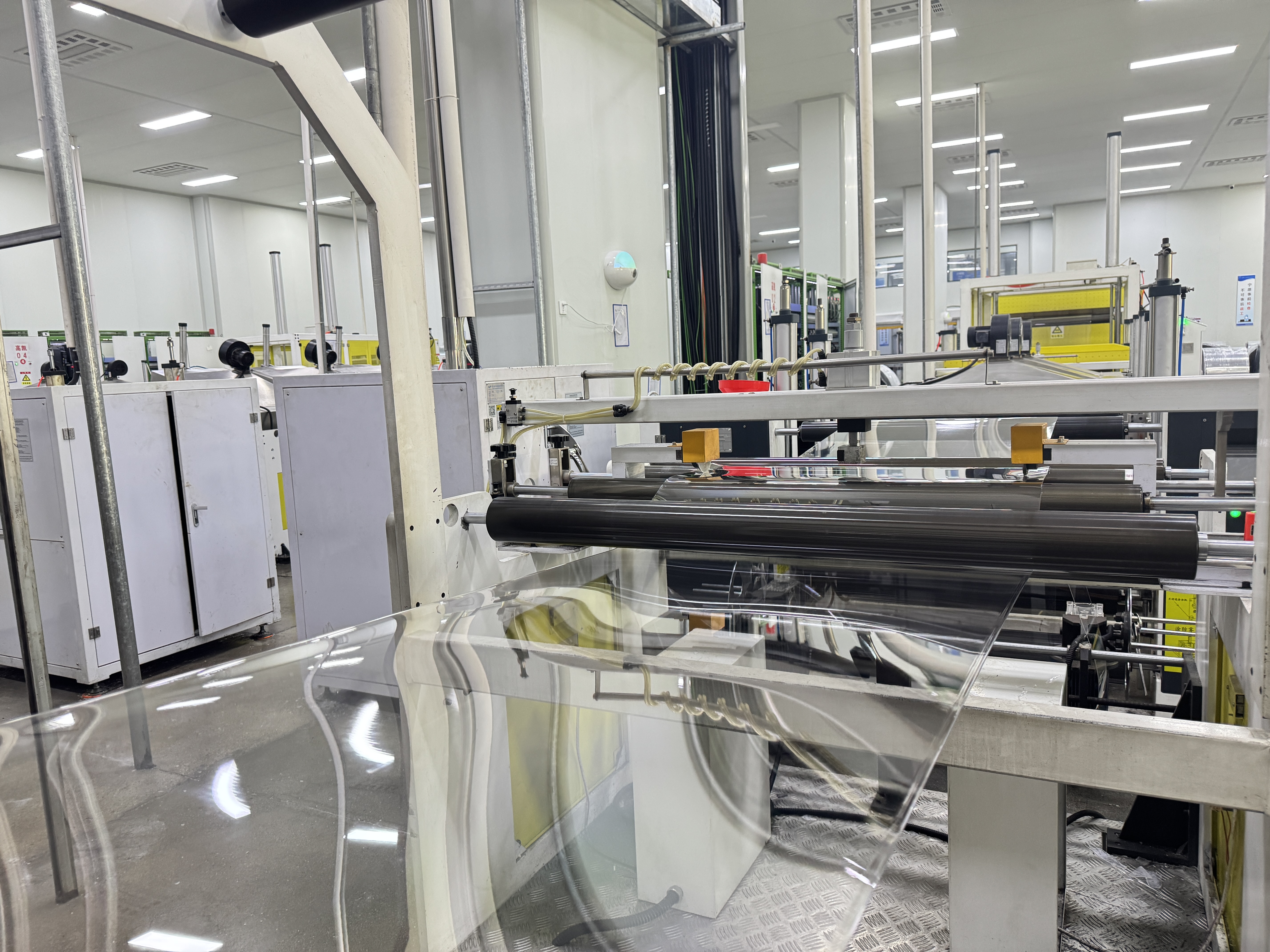
The photos below show sheet rolls, feed and production equipment. Read them alongside the packaging shapes and tool surfaces above; they are separate references, not a verified sequence from one project.
Scroll sideways to explore the images. Select an image to enlarge it.
Production equipment
Views of the line and its working parts provide manufacturing context. A project sample is used to check the resulting pack.
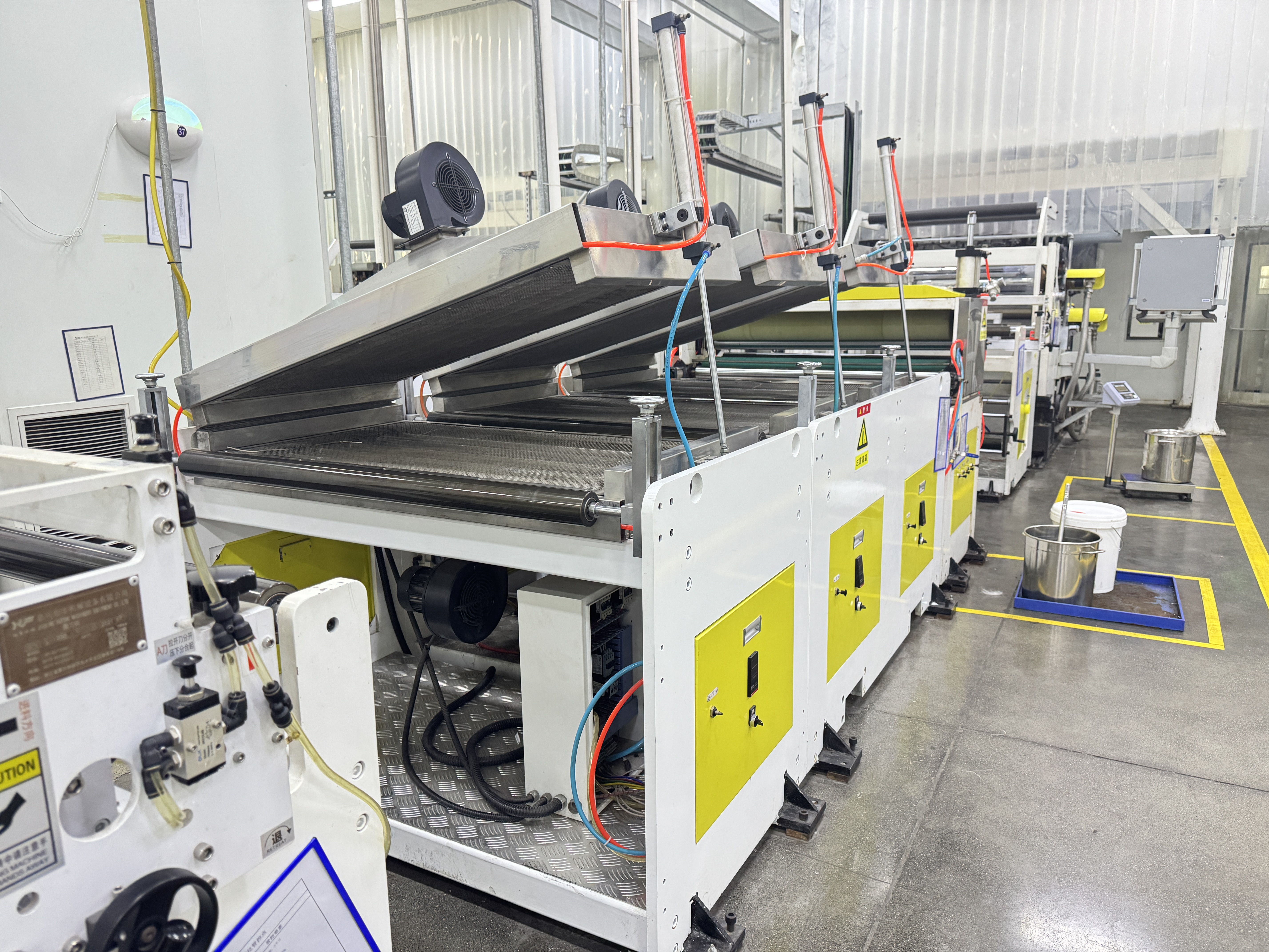
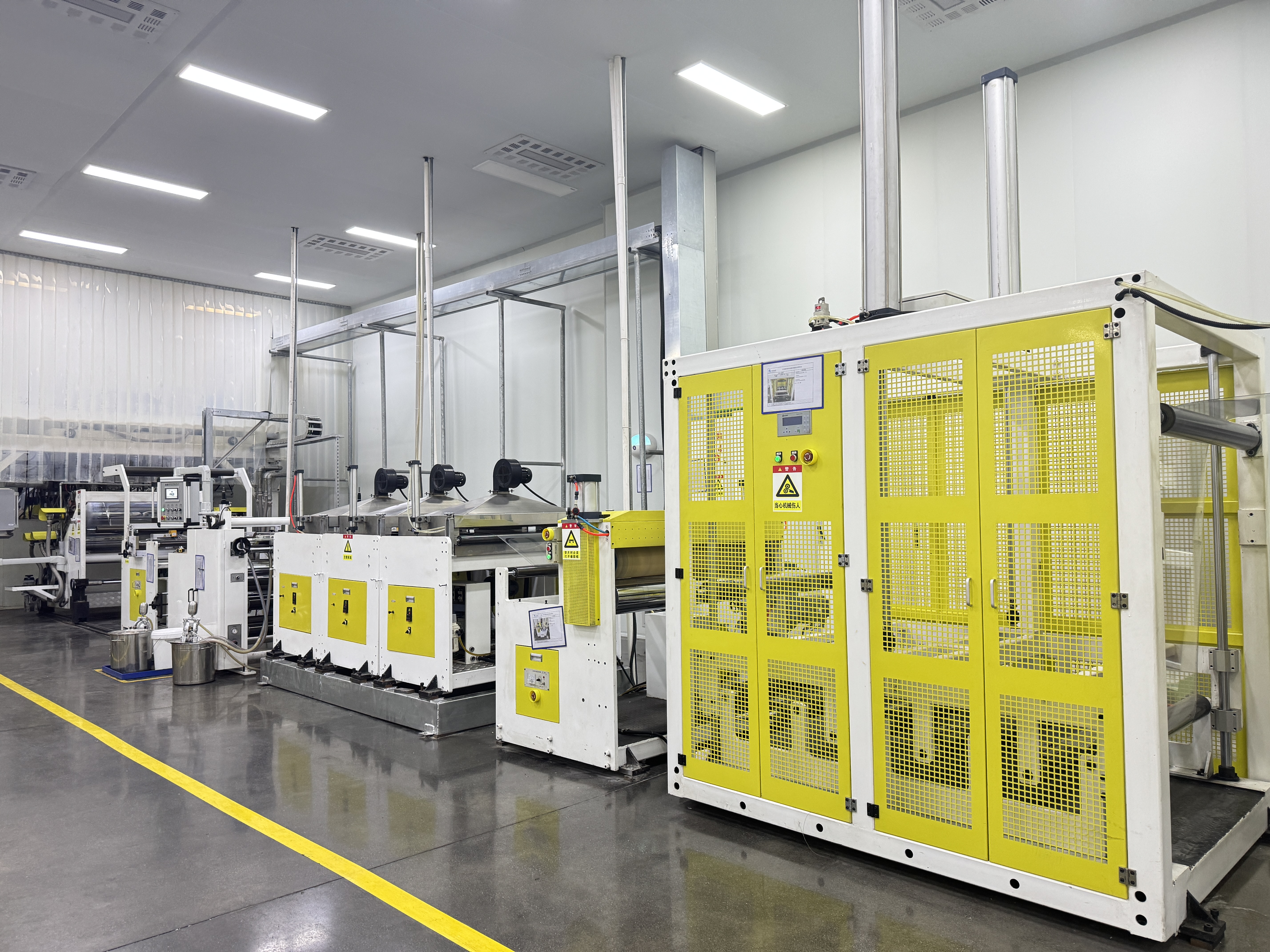
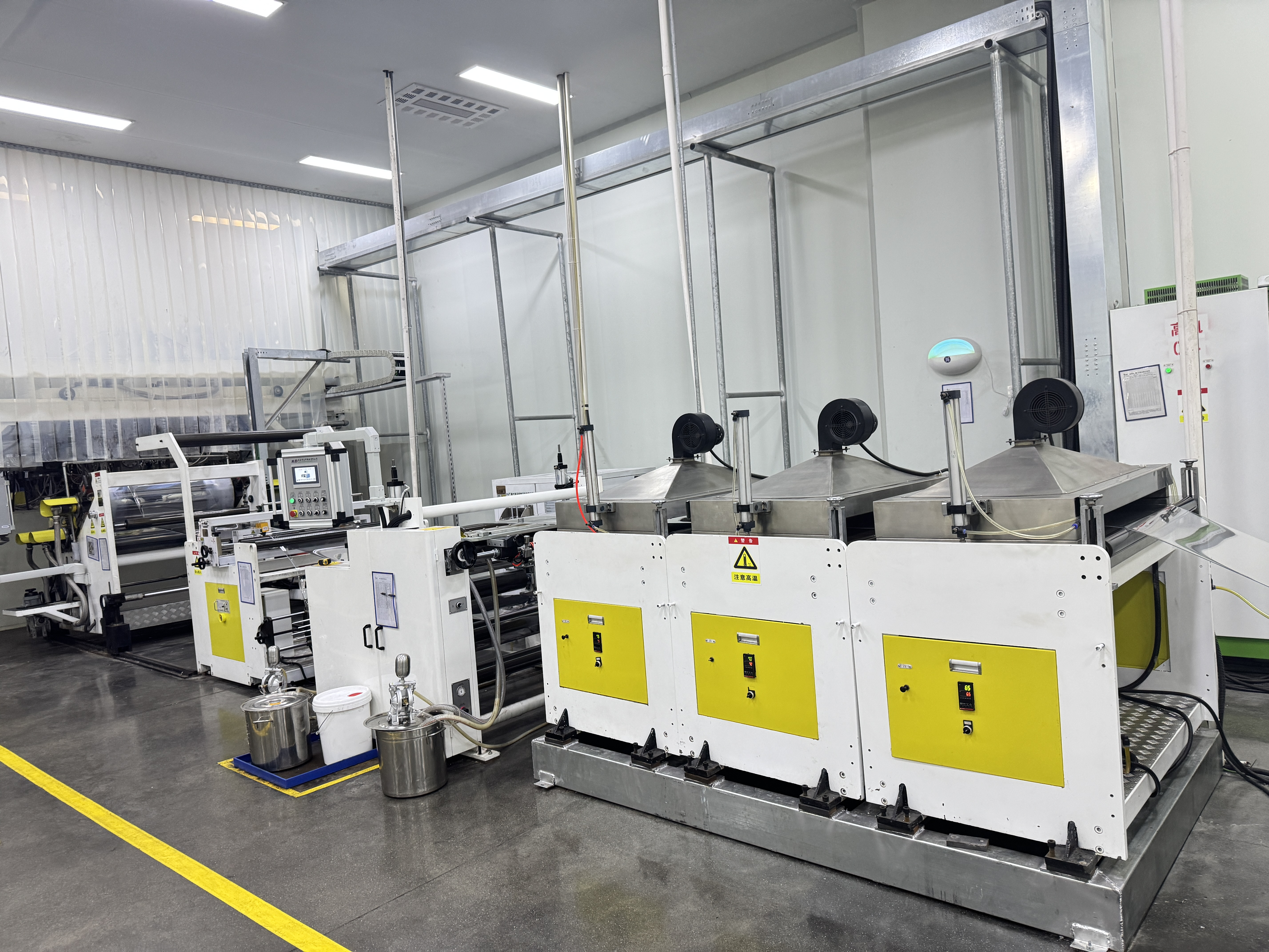
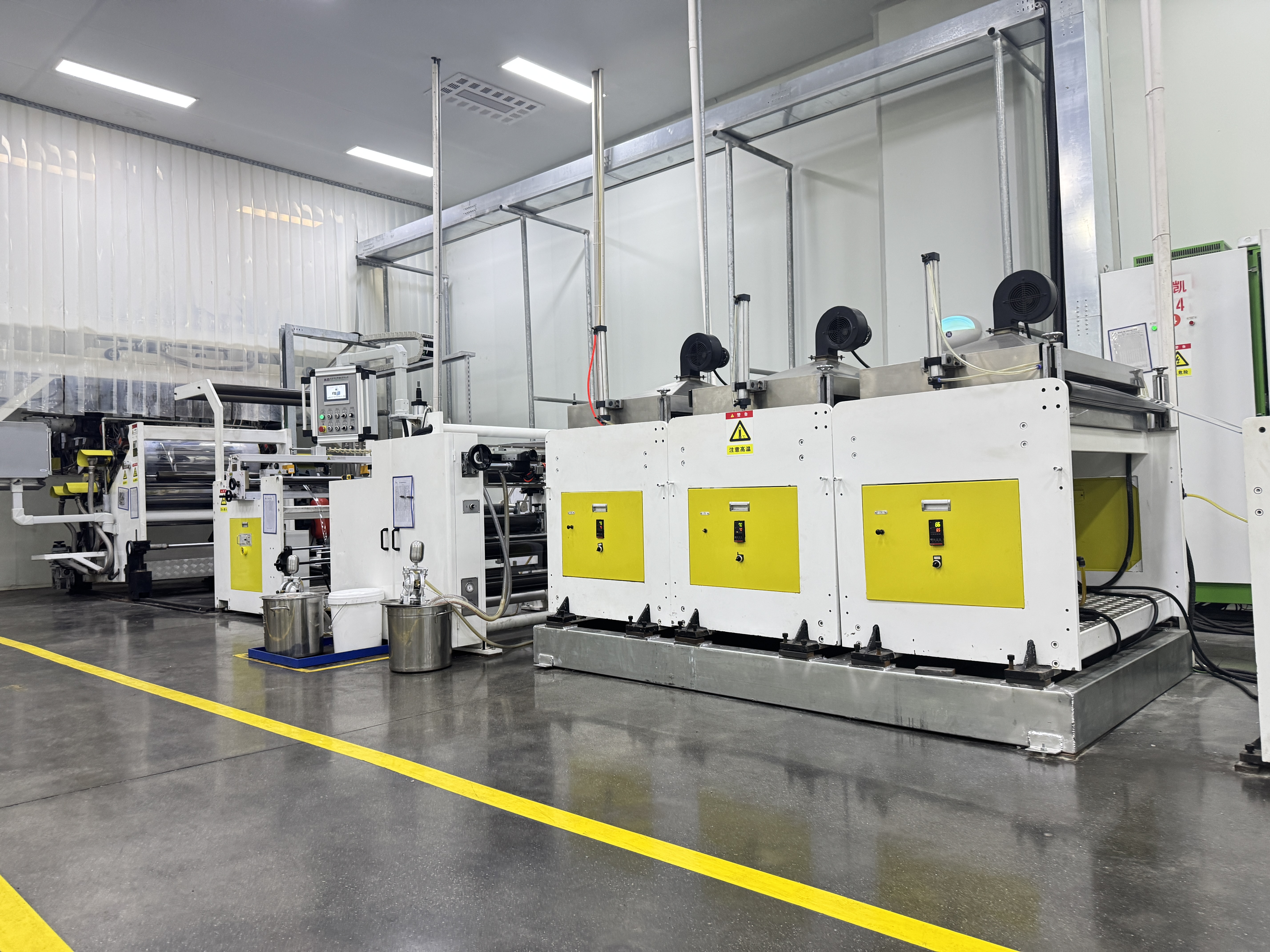
Scroll to see all 8 views →
Sheet rolls and feed
These photos show storage and the sheet path at the equipment. Material grade and thickness are agreed for the intended pack.
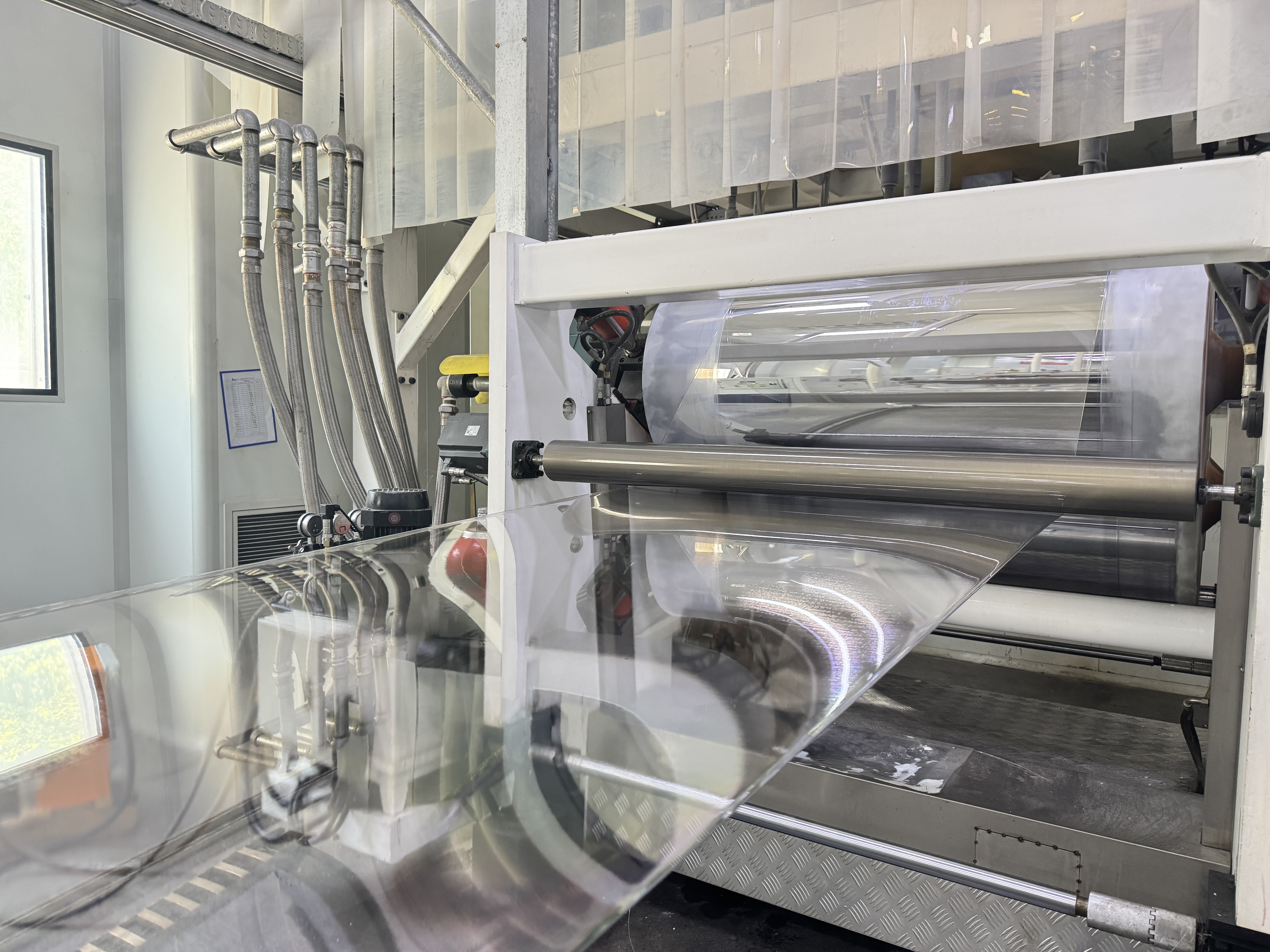
Scroll to see all 5 views →
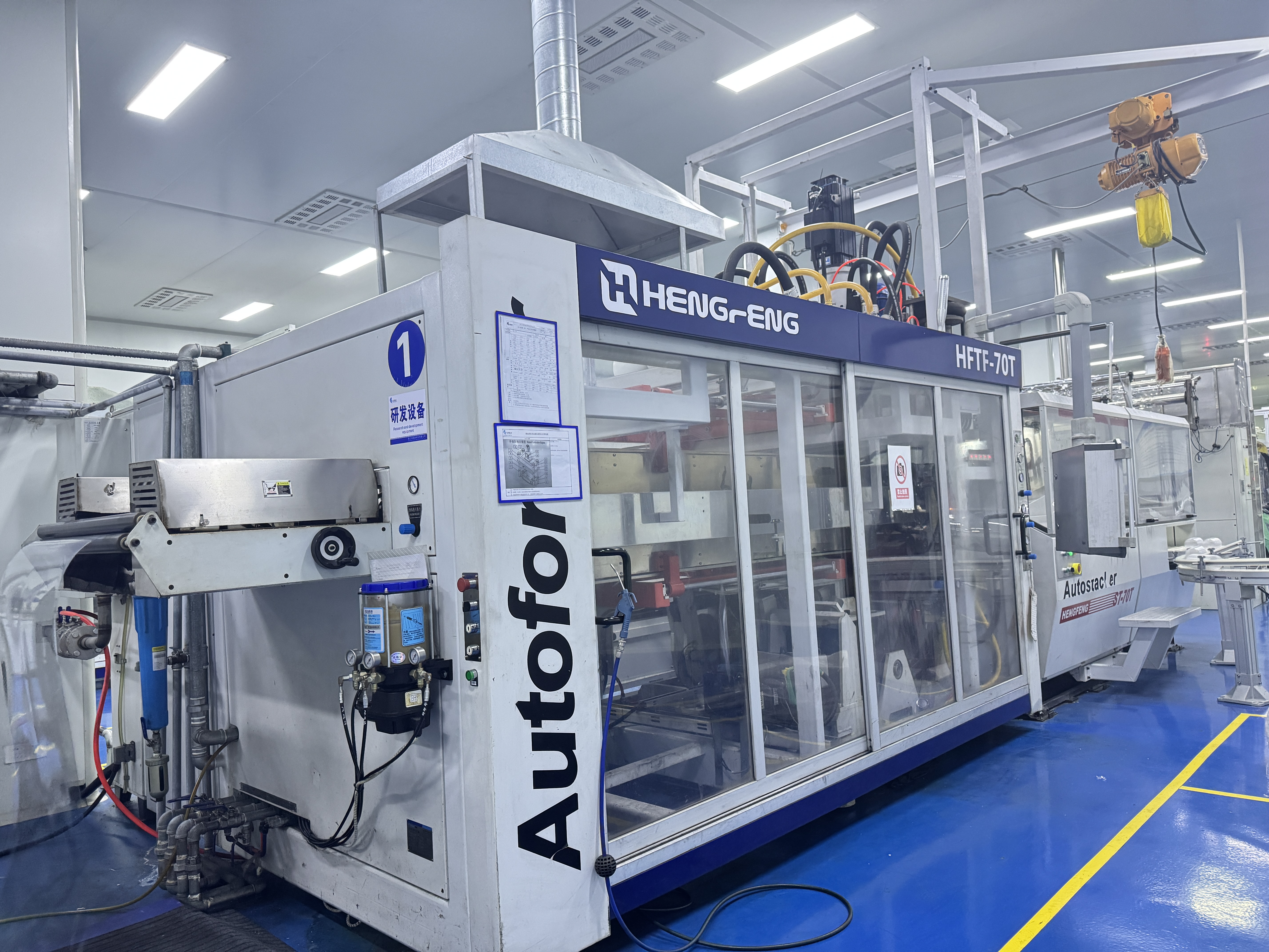
Thermoforming machine on the floor
This photo shows the machine and surrounding equipment; use the packaging views above to discuss the pack shape.